
Built (#06/2026)
Short, interesting, engineering & infrastructure posts. One email every Sunday

Japanese Seismic Control Methods
Nice video to see a real-life example of why Japan leads the world in earthquake-resilient design. And it doesn’t rely on a single method. It uses a combination of three core systems: seismic resistance, seismic damping, and seismic isolation.
Each of them has a different engineering approach to managing seismic energy.
1️⃣ Seismic Resistance (Taishin)
Structures are designed to be stiff and strong. Reinforced with steel, cross-bracing, and moment-resisting frames.
This approach absorbs seismic loads solely through strength.
But high rigidity means higher stress and more damage.
1️⃣ Seismic Damping (Seishin)
These include oil dampers, tuned mass dampers, and friction devices that convert kinetic energy into heat or controlled friction.
Think of it like shock absorbers in a car, but scaled up to handle thousands of tonnes of structural mass.
3️⃣ Seismic Isolation (Menshin)
Entire buildings are built on flexible base isolators.
Often made of laminated rubber and lead cores, which decouple the structure from ground motion. During a quake, the ground moves, but the building barely does. This method can reduce seismic acceleration by up to 90%.
These systems are often used in combination. Engineers might pair base isolation with damping, or use resistance as the first line of defence.
Japan’s seismic engineering is a layered defence system: mechanical, structural, and strategic.
The result is a safer building, often reusable after major earthquakes.
Eerie Sounds of the Verrazzano-Narrows Bridge
Earphones in for this one. Listen to the otherworldly, eerie sounds of the Verrazzano-Narrows Bridge in NY as the expansion joints creak, shift, and moan under high winds.
It's beautifully scary.
Suspension bridges aren't rigid and can move significantly in high winds.
The bridge has the 18th-longest main span in the world and the longest in the Americas.
And despite being only slightly longer than the Golden Gate Bridge, the Verrazzano–Narrows Bridge could carry a 75% greater load than the former could.
This swaying is similar to the Tacoma-Narrows Bridge, which behaved similarly and ultimately collapsed due to aeroelastic or torsional flutter. That footage has been used as a case study in almost every engineering class in history since the 1940s.
What you see here is a similar phenomenon, except that modern bridge designers have learned from past mistakes, and the movement here is perfectly acceptable and within design tolerances.
So it won't dramatically fall!
The bridge does close as a precaution when the wind is too high, though.
Structural and bridge engineers model and calculate expected stresses, strains, and movements, and design accordingly.
A rigid bridge would be a problem.
This is not.
In the same way, even large bends on an aeroplane wing are perfectly normal behaviour (even if disconcerting)
I think this is super cool.
-
For over 50 years, from its opening in 1964 until late 2018, the bridge was officially spelt with only one "z" (Verrazano) because of a mistake in the original construction contract.
The span is named for Giovanni da Verrazzano, who in 1524 was the first European explorer to enter New York Harbor and the Hudson River.
Railway Wheel Contact Point
The contact point between the railway wheel and rail is shockingly small. A steel wheel carrying tens of tonnes meets a steel rail over a contact patch roughly the size of a postage stamp.
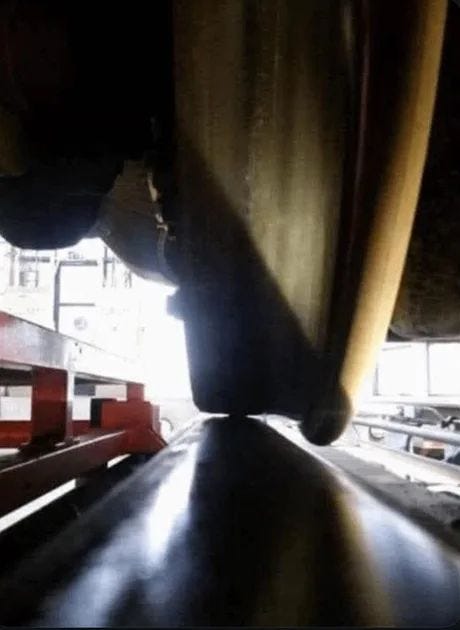
Typically around 10 to 20 mm wide and a few millimetres long, depending on load, wheel profile and rail condition.
This tiny area carries axle loads of 150 to 250 kN on modern freight trains.
The result is contact pressures that can exceed 1 GPa, comparable to those in hardened bearings or gear teeth.
The physics behind it is Hertzian contact theory.
That means the two curved steel surfaces touch, deform elastically, and spread the load just enough to avoid plastic failure under normal conditions.
"Elastically" just means the material deforms and bounces back to its original shape, like a balloon, after you make a little indent with your thumb.
And "plastically" means it does not bounce back, like playdough you indent.
The wheel is slightly conical, and the rail head is carefully profiled.
That geometry allows trains to self-steer through curves while keeping the contact patch controlled and predictable.
From an engineering perspective, this is why rail steel is so specialised.
It needs high hardness for wear resistance, enough toughness to resist cracking, and fatigue strength to survive billions of load cycles.
It also explains why surface defects matter so much.
A small flat on a wheel or a corrugation in the rail concentrates stress even further, accelerating rolling contact fatigue and spalling.
Lubrication plays a subtle role, too.
Railhead friction must be high enough for traction and braking, but low enough to limit wear and noise. That balance is one of the quiet battles in railway engineering.
What looks simple is actually one of the most highly stressed interfaces in everyday infrastructure.
Shell LNG Prelude
At 488 meters long by 74 meters wide, the 600,000-tonne Prelude FLNG is the largest offshore structure ever built. To put that in perspective, Prelude is longer than four full-size football fields laid end to end, and it displaces six times as much water as the largest aircraft carrier.
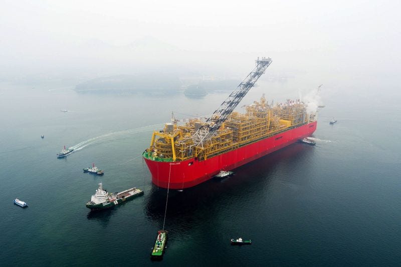
The large scale only makes sense once you understand what it is actually there to do.
Prelude is a floating liquefied natural gas facility (hence the FLNG)
Instead of piping gas ashore for processing, the entire production chain is on the vessel. Gas is produced from subsea wells, processed, dried, cooled to around minus 162 C, and stored onboard as LNG.
This approach removes the need for long export pipelines and onshore plants.
For remote gas fields with modest reserves, that tradeoff can make a marginal project viable.
Prelude is permanently stationed over the Prelude and Concerto gas fields, about 475 kilometres north east of Broome off the coast of Western Australia.
Once on location, it is not expected to leave for its entire design life of around 25 years.
That raises the obvious engineering problem:
How do you keep a structure of this size in position in deep water, exposed to cyclones, waves, and currents?
The answer is a turret mooring system.
A massive internal turret passes through the hull near the bow and is anchored to the seabed by multiple mooring lines arranged radially.
These lines consist of a chain and steel wire, connected to large suction piles driven into the seabed.
The vessel itself is not rigidly fixed to the seabed.
Instead, it weathervanes freely around the turret, always aligning itself with wind, waves, and current. Just like a weathervane on the roof, it will turn toward the prevailing wind.
This significantly reduces environmental loads on the hull and moorings, which is critical for fatigue life.
All subsea flowlines and umbilicals also connect through the turret.
This allows continuous production while the vessel rotates, without twisting or overstressing the connections.
On deck, the topsides are closer to a refinery than a ship.
The processing modules weigh tens of thousands of tonnes and include compressors, heat exchangers, cryogenic equipment, and utilities that would normally sit on land.
Integrating all of this into a floating hull pushed naval architecture and offshore engineering into territory that had never been attempted at this scale.
Prelude is controversial, expensive, and operationally complex.
But from an engineering perspective, it is a full industrial plant, permanently moored in open ocean, designed to survive some of the harshest offshore conditions on the planet.
That alone makes it one of the most ambitious offshore engineering projects ever executed.